IMAGE INTENSIFIERS
Image Diode
High resolution and excellent dynamic range
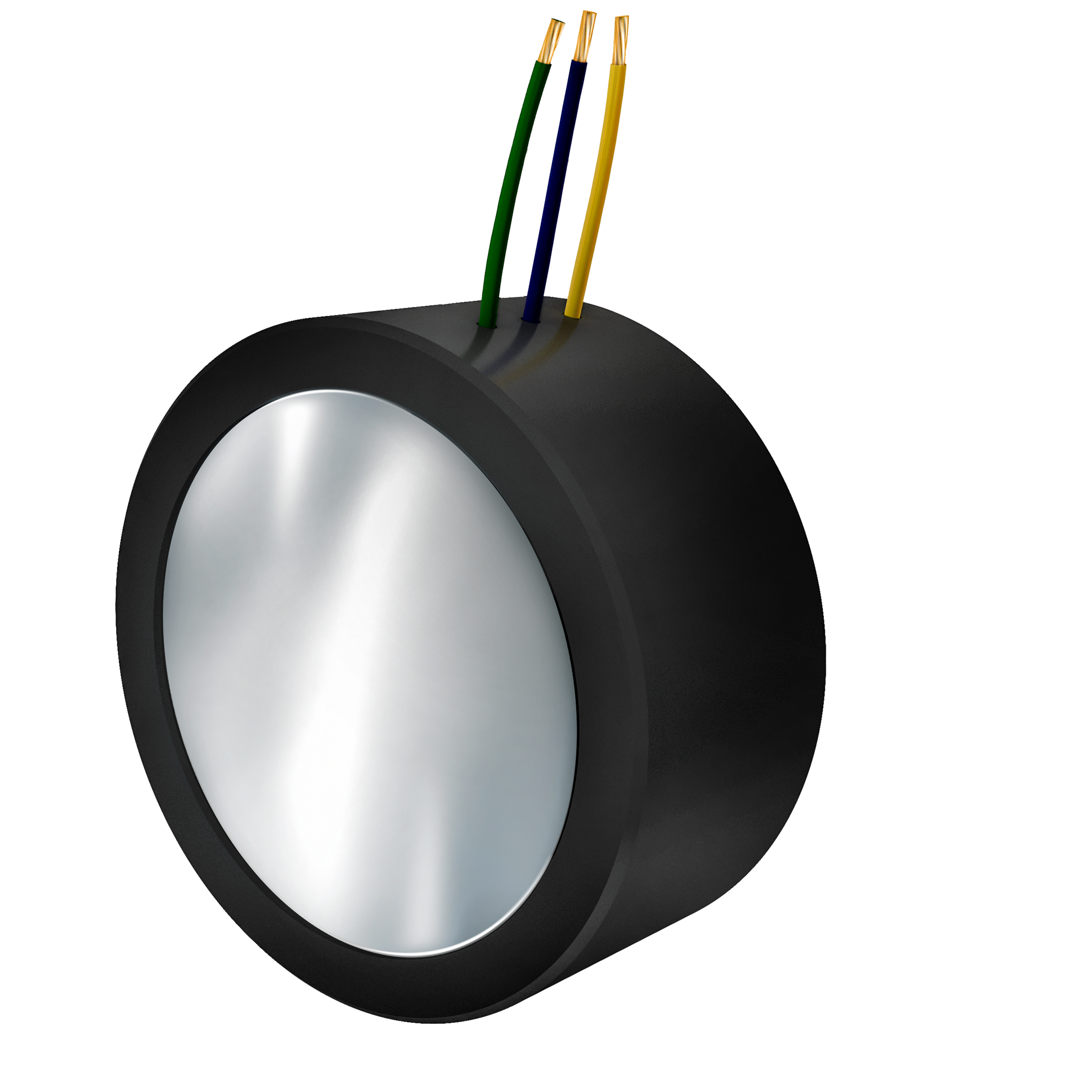
With high resolution and excellent dynamic range, these devices are often known as Generation I image intensifiers. Typically they are used in series with other types of intensifiers or used to convert UV or infrared into visible light.

Features
Range of active diameters available
18 mm, 25 mm, 40 mm
High dynamic range and brightness
"Booster" configurations available
can be coupled to Photek image intensifiers to boost brightness
High resolution
as compared to MCP-based intensifiers
Wide choice of spectral response
across UV, Solar Blind, Visible and NIR
Customised
for integration with your camera or as a module
Applications
- High speed intensified imaging (“Booster” Tube)
- Wavelength conversion, from UV or Infrared to Visible (Converter Tube)
Overview
With high resolution and excellent dynamic range, image diodes achieve light gain of > 10×. This is achieved without microchannel plate multiplication of electrons, instead utilising a high-voltage electric field.
Image diodes have two primary uses:
“Booster” Tube: Image diodes are often used in conjunction with microchannel plate (MCP) based intensifiers to further increase image brightness.
Converter Tube: the image diode is used to convert non-visible (e.g. ultraviolet) light into visible light.
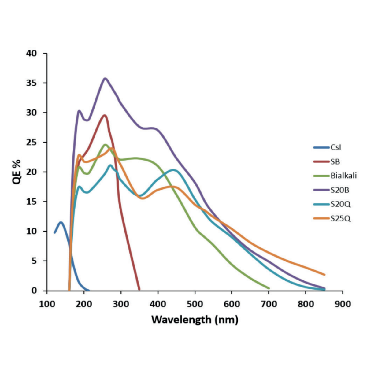
A range of photocathodes and input window materials enables a wide choice of spectral responses to suit most applications.
The phosphor and output window type can be chosen as to fit with the imaging or observation method.
Range
The table below outlines the Part Number format for our standard product range. To talk further about these products, or bespoke solutions for your application, then please Contact us.
Example: ID025/F/S20/P43/G
is a 25mm diameter image diode, with a fibre optic input window, S20 photocathode, and P43 phosphor, with a glass output window.
TYPE | Size | Input | Photocathode | Phosphor | Output |
ID0 | 18 | IFO (Fibre Optic) | SB (Solar Blind) | P43 | IFO (Fibre Optic) |
25 | Q (Fused Silica) | BI (Bialkali) | P46 | G (Glass) | |
40 | S20B | P47 | ITA (Fibre Taper) | ||
S20 | (Others upon request) | ||||
S25 |
Specifications
Type | Peak Wavelength (nm) | Photons/Electron @ 5kV | Decay Characteristic |
P20 | 540 | 320 | Fast initial decay with long decay at low level. 1ms to 1%. |
P43 | 548 | 240 | 1.2 ms/decade, true exponential |
P46 | 530 | 55 | 300 ns |
P47 | 410 | 64 | 80 ns |
Phosphor of the Coupled Image Intensifier | Peak Phosphor Wavelength | Image Diode Photocathode | Image Diode Phosphor | Typical Image Diode Photon Gain (glass output) | Typical Voltage |
P43 | 548 | S20 | P43 | 102 | +8 kV |
P46 | 530 | S20 | P46 | 27 | +8 kV |
P47 | 410 | S20B | P47 | 65 | +8 kV |
Conversion | Photocathode | Typical Applied Voltage | Quantum Efficiency (QE) | Photon Gain with glass output (at stated wavelength) (W/W) |
(%) (nm) | P20 P43 P46 | |||
Deep UV | SB | +8kV | 30 254 | 365 274 65 |
Broad UV | S20B | +8kV | 28 350 | 342 255 57 |
NIR | S25 | +8kV | 4 800 | 49 38 8 |
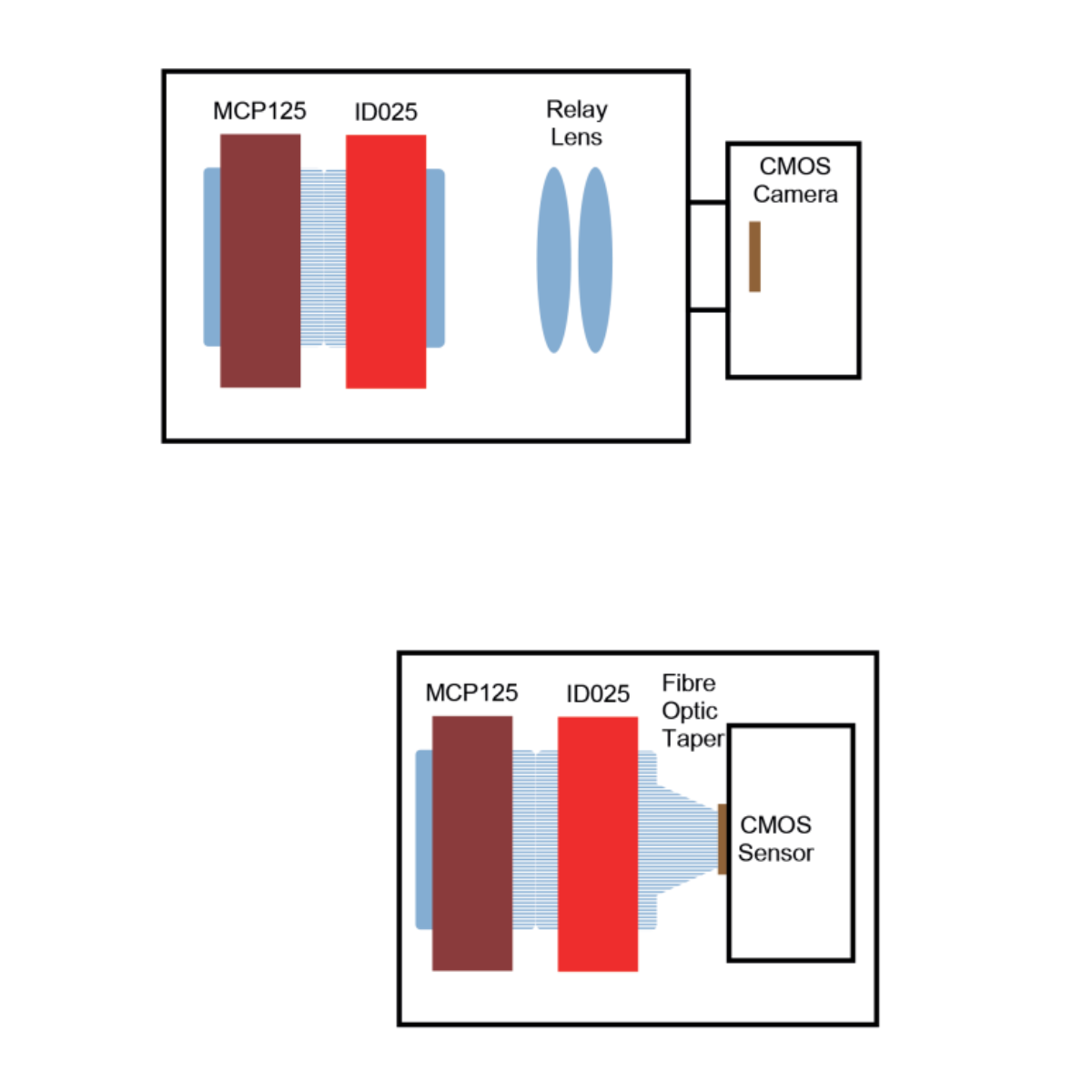
Configurations for an Intensified High Speed Camera

Top Drawing; Typical configuration
Shown is an MCP125 image intensifier with Fibre Optic output coupled to an ID025 Image Diode having a Fibre Optic input. The MCP125 and ID025 are bonded together providing high optical gain and dynamic range suitable for high speed imaging. A Glass output on the ID025 is coupled to a high speed camera using a relay lens, typically via a lens mount. The camera can be used with or without the intensifiers.
Bottom Drawing; Alternative configuration
Shown is an MCP125 image intensifier with fibre optic output coupled to an ID025 Image Diode having both Fibre Optic input and output. The MCP125 and ID025 are bonded together providing high optical gain and dynamic range suitable for high speed imaging. A Fibre Optic is used to couple the output of the ID025 to a high speed CMOS sensor resulting in a compact but permanent solution.
Photocathode Response

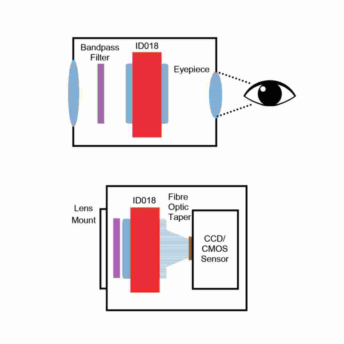
Configurations for an Image Converter

Top Drawing; Typical configuration for a direct view Image Converter.
Shown is an ID018 Image Diode with glass input and output optics. The Image Diode converts either Ultraviolet or Near Infrared to visible wavelengths for viewing by eye. Often a bandpass filter is used to reject light at wavelengths that are not of interest.
Bottom Drawing; Alternative configuration for an Image Converter with integral CCD/CMOS camera for applications where direct viewing is not required.
Shown is an ID018 Image Diode having a Glass input and Fibre Optic output. A Fibre Optic taper is used to couple the output of the ID018 to a CCD/CMOS sensor resulting in a compact digital output image converter.
Documentation
Related Topic

Application Title
Lorem ipsum dolor sit amet, consec tetuer adipiscing elit, sed diam nonummy nibh euismod tincidunt.

Application Title
Lorem ipsum dolor sit amet, consec tetuer adipiscing elit, sed diam nonummy nibh euismod tincidunt.

Application Title
Lorem ipsum dolor sit amet, consec tetuer adipiscing elit, sed diam nonummy nibh euismod tincidunt.

Application Title
Lorem ipsum dolor sit amet, consec tetuer adipiscing elit, sed diam nonummy nibh euismod tincidunt.


